
The impedance of a transformer is stated on the nameplate of most power transformers. The nameplate below is from a delta-wye transformer with an impedance of 5.8%. In this paper, I will attempt to explain transformer impedance and how its value is derived.
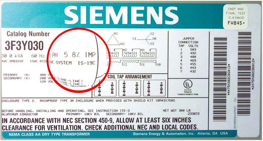
The impedance of a transformer can be calculated by measuring the voltage drop across a winding at full load and is expressed as a percentage of the rated voltage. In the above example, we would expect the voltage drop on the secondary at full load to be approximately 12 volts or 5.8% of 208 volts and the voltage drop across the primary to be nearly 28 volts or 5.8% of the primary voltage. It may be easier to think of the transformer as a source with an impedance connected in series. The voltage divides between the source impedance and the load as shown in the following illustration:
The source impedance is the sum of the winding resistance and leakage reactance and is expressed as a percentage of the rated voltage. This will also be the voltage that must be applied to a shorted transformer in order to circulate full-load current.
Measuring Impedance
The impedance is measured by means of a short circuit test, as shown below. A voltmeter is placed across the primary winding and the secondary winding is shorted. A voltage at the transformer’s rated frequency is applied to the primary winding using a variable transformer. Applied voltage is increased until the rated full load current flows through the shorted winding (measured with an ammeter). The percentage impedance can then be calculated with the following formula:
Z% = (Test Voltage/Rated Voltage) x 100
The Effect of System Impedance
The impedance of a transformer has a major effect on available system fault levels. It determines the maximum value of current that will flow under fault conditions. It is also the most common cause of voltage drop when the load is increased.
It is easy to calculate the maximum current that a transformer can deliver under symmetrical fault conditions. By way of example, consider a 20 kVA transformer with an impedance of 5% and a secondary voltage of 480v. The maximum fault level available on the secondary side is:
20 kVA x 100/5 = 400 kVA
or simply
20 kVA/.05 = 400 kVA
From this figure the available fault currents can be calculated as follows:
1-phase: ISCA = VA/EL-L
3-phase: ISCA = VA/EL-L x 1.732
So, if this were a 1-phase transformer the short circuit current would be:
400,000VA/480v = 833.3A vs a full load rating of 20,000/480 = 41.7A
For a 3-phase transformer the short circuit current would be:
400,000VA/480v x 1.732 = 481.14A vs a full load rating of 20,000/480 x 1.732 = 24.06A
Obviously, a transformer with a lower impedance will have higher available fault currents and vice versa. These calculations only deal with phase to phase faults (symmetrical faults). Non-symmetrical faults (phase-earth, phase-phase etc) require more complex calculations and are beyond the scope of this article.
As noted in the article, a practical transformer can be viewed as an ideal power source in series with a resistance. When a load is connected across the transformer output, it is essentially placed in series with the transformer impedance and the applied voltage will divide between the transformer impedance and the load impedance in accordance with Ohm’s Law.